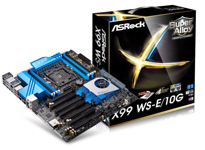
ASRock X99 WS-E/10G Motherboard Review: Dual 10GBase-T for Prosumers
by Ian Cutress on December 15, 2014 10:00 AM EST- Posted in
- Motherboards
- IT Computing
- Intel
- ASRock
- Enterprise
- X99
- 10GBase-T
For a number of months I have been wondering when 10GBase-T would be getting some prime time in the consumer market. Aside from add-in cards, there was no onboard solution, until ASRock announced the X99 WS-E/10G. We were lucky enough to get one in for review.
10GBase-T is somewhat of an odd standard. Based on upgraded RJ-45 connections, it pushes the standard of regular wired networking in terms of performance and capability. The controllers required for it are expensive, as the situations that normally require this bandwidth tend to use different standards that afford other benefits such as lower power, lower heat generation and more efficient signaling standards. Put bluntly, 10GBase-T is hot, power hungry, expensive, but ultimately the easiest to integrate into a home, small office or prosumer environment. Users looking into 10GBase-T calculate cost in hundreds of monies per port, rather than pennies, as the cheapest unmanaged switches cost $800 or so. A standard two port X540-T2 PCIe 2.0 x8 card can cost $400-800 depending on your location, meaning a minimum $2000 for a 3 system setup.
The benefits of 10GBase-T outside the data center sound somewhat limited. It doesn't increase your internet performance, as that is determined by the line outside the building. For a home network, its best use is in computer to computer data transfer. Normally a prosumer environment might have a server or workstation farm for large dataset analysis and GBit just isn't enough. Or the most likely home scenario is streaming lossless 4K content to several devices at once. For most users this sounds almost a myth, but for a select few it is a reality, or at least something near it. Some users are teaming individual GBit ports for similar connectivity as well.
Moving the 10GBase-T controller and ports ultimately frees up PCIe slots for other devices, and makes integration easier, although you lose the ability to transfer the card to another machine if needed. The X540-BT2 used in the X99 WS-E/10G has eight PCIe 3.0 lanes on a 40 PCIe lane CPU, but can also work with four lanes via the 28-lane i7-5820K CPU if required. Using the controller on the motherboard also helps with pricing, providing an integrated system and hopefully shaving $100 or so from the ultimate cost. That being said, as it ends up in the high end model, it is aimed at those where hardware cost is a minimal part of their prosumer activities, where an overclocked i7-5960X system with 4+ PCIe devices is par for the course.
ASRock X99 WS-E/10G Overview
In an ideal testing scenario, we would test motherboards the same way we do medicine – with a double blind randomized test. In this circumstance, there would be no markings to give away who made the device, and during testing there would be no indication of the device either. With CPUs this is relatively easy if someone else sets the system up. With motherboards, it is almost impossible due to the ecosystem of motherboard design that directly impacts expectation and use model. Part of the benefit of a system is in the way it is presented as well as the ease of use of software, to the point where manufacturers will spend time and resources developing the extra tools. Providing the tools is easy enough, but developing it into an experience is an important aspect. So when ASRock presents a motherboard with 10GBase-T, the main key points here are ‘10GBase-T functionality’ coming from ‘ASRock’.
Due to the cost of the 10GBase-T controller, the Intel X540-BT2, ASRock understandably went high-end in their first implementation. This means a full PCIe 3.0 x16/x16/x16/x16 layout due to the use of two PLX 8747 chips that act as FIFO buffer/muxes to increase the lane count. For those new to PLX 8747 chips, we went in-depth on their function when they were first released which you can read here. These PLX chips also are quite expensive, at least adding $40 each to the cost of the board for the consumer, but allow ASRock to implement top inter-GPU bandwidth. This means that from the 40 PCIe lanes of an LGA2011-3 CPU, 8 go to the X540-BT2 and 16 each go to the PLX chips which output 32 each. For users wanting to go all out with single slot PCIe co-processors, the X99 WS-E/10G will allow an x16/x8/x8/x8/x8/x8/x8 arrangement.
If the WS in the name was not a giveaway, with the cost of these extra controllers, ASRock is aiming at the 1P workstation market. As a result the motherboard has shorter screws to allow 1U implementation and full Xeon support with ECC/RDIMM up to 128GB. The power delivery package is ASRock’s 12-phase solution along with the Super Alloy branding indicating XXL heatsinks as well as server grade components. The two PLX chips are cooled by a large heatsink with a small fan, although this can be disabled if the users cooling is sufficient. Another couple of nods to the WS market is also the two Intel I210 network interfaces with the dual 10GBase-T, affording a potential teaming rate of 22 Gbps all in. There is also a USB Type-A port sticking out for license dongles as well as a SATA DOM port. TPM, COM and two BIOS chips are also supported.
On the consumer side of the equation, the chipset IO is split into four lanes for an M.2 x4 port, the two Intel I210 NICs mentioned before and a SATA Express implementation. The M.2 slot has some PCIe sharing duties with a Marvell 9172 SATA controller as well, meaning that using the Marvell SATA ports puts the M.2 into x2 mode. The board has 12 total SATA ports, with 6 PCH RAID capable, four PCH non-RAID capable and two from the Marvell. Alongside this is eight USB 3.0 ports, four from two onboard headers and four ports on the rear panel from an ASMedia ASM1074 hub. An eSATA port is on the rear panel as well, sharing bandwidth with a non-RAID SATA ports. Finally the audio solution is ASRock’s upgraded ALC1150 package under the Purity Sound 2 branding.
Performance wise, ASRock uses an aggressive form of MultiCore Turbo to score highly in our CPU tests. Due to the 10G controller, the power consumption is higher than other motherboards we have tested, and it also impacts the DPC Latency. USB 2.0 speed was a little slow, and the audio had a low THD+N result, but POST times were ballpark for X99. The software and BIOS from ASRock followed similarly from our previous ASRock X99 WS review.
The 10GBase-T element of the equation was interesting, given that for PC-to-PC individual transfers from RAMDisk to RAMDisk peaked at 2.5 Gbps. To get the most from the protocol the data transfer requires several streams (more than one transfer function to allow for interleaving), at least four for 6 Gbps+ or eight for 8 Gbps+. One bottleneck in the transfer is the CPU, showing 50% load on an eight-thread VM during transfer using five streams, perhaps indicating that an overclocked CPU (or something like the i7-4790K with a higher threaded speed) might be preferable.
Whenever a motherboard company asks what a user looks for in a motherboard, I always mention that if they have a particular need, they will only look at motherboards that have the functionality. Following this, users would look choosing the right socket, then filter by price, brand, looks and reviews (one would hope in that vague order). The key point here being that the X99 WS-E/10G caters to that specific crowd that need a 10GBase-T motherboard. If you do not need it, the motherboard is overly expensive.
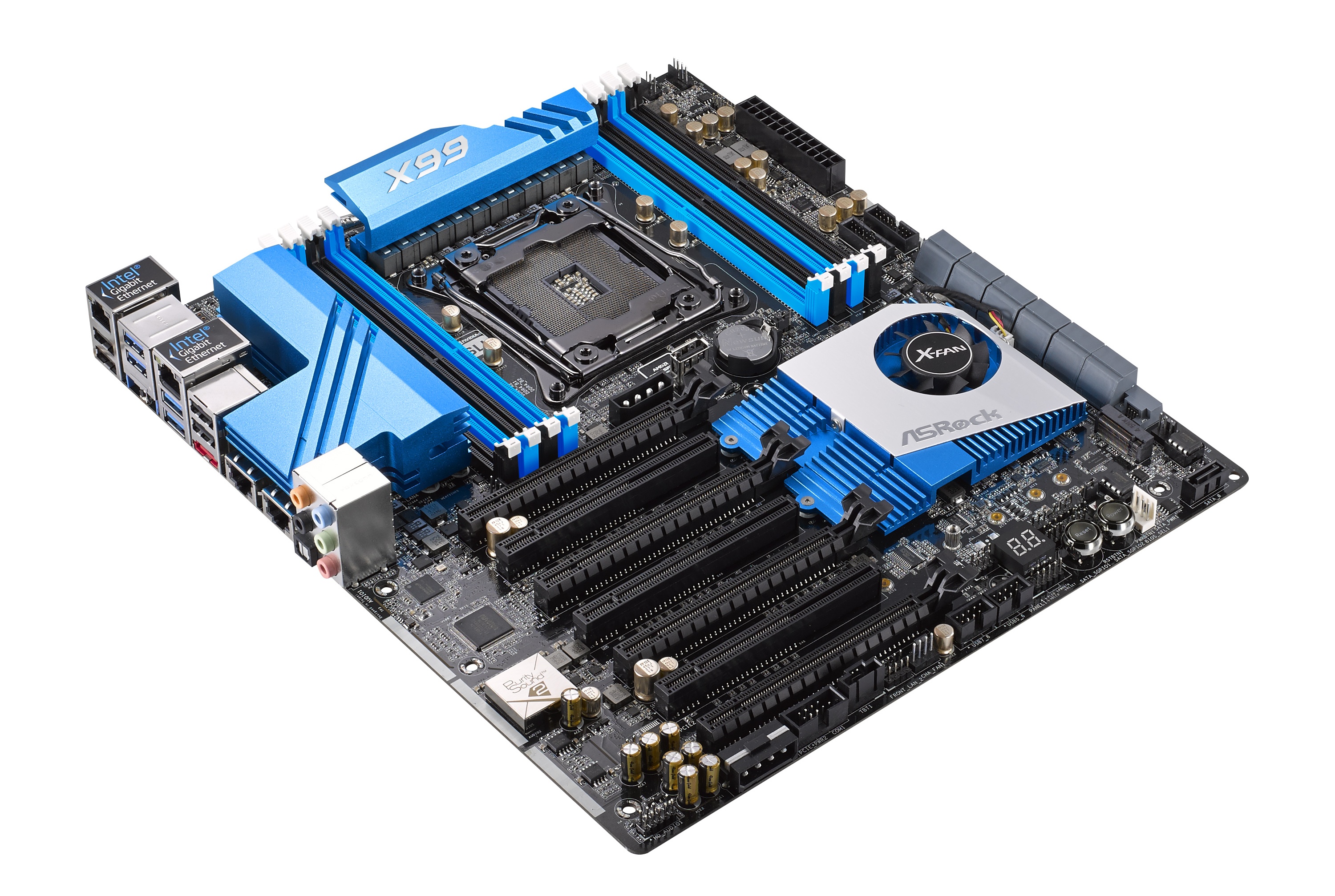
Visual Inspection
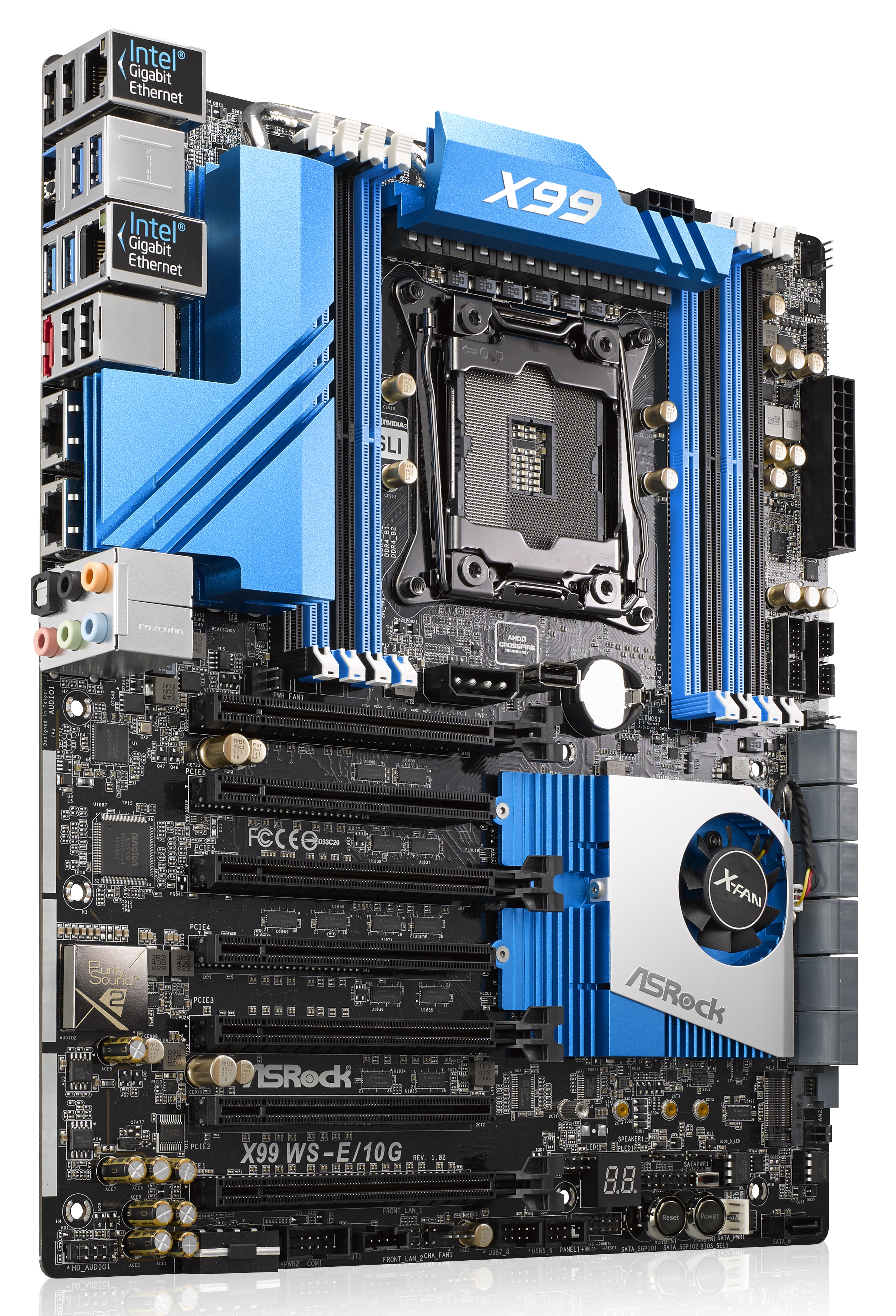
Motherboards with lots of additions tend to be bigger than usual, and the WS-E/10G sits in the E-ATX form factor. This allows the addition of the X540-BT2 controller and the two PLX 8747 switches with more PCB room for routing. As the 10G controller is rated at 14W at full tilt it comes covered with a large heatsink which is connected via a heatpipe to the heatsink covering the power delivery. The smaller heatsink covering the chipset and two PLX chips is not connected to the others, however it does have a small fan (which can be disconnected) to improve cooling potential.
As this motherboard is oriented towards the workstation market we get features such as COM and TPM headers, with a total of five fan headers around the motherboard. The two CPU fan headers, one four-pin and one three-pin, are at the top right of the board, with a 3-pin CHA header just above the SATA ports and another just below. The final header is on the bottom panel, this time four-pin. The ‘white thing that looks like a fan header’ at the bottom of the board is actually used for SATA DOM power. Note that HDD Saver does not feature on this motherboard.
The DRAM slots are single-sided with the latches due to the close proximity of the first PCIe slot, which means that users should ensure that their DRAM is fully pushed in at both ends. Next to the DRAM is one of the PCIe power connectors, a horrible looking 4-pin molex connector right in the middle of the board. I asked ASRock about these connectors (because I continually request they be replaced) and ASRock’s response was that they would prefer a single connector at the bottom but some users complain that their cases will not allow another connector angled down in that location, so they put one here as well. Users should also note that only one needs to be connected when 3+ PCIe devices are used to help boost power. I quizzed them on SATA power connectors instead, or a 6-pin PCIe, however the response was not enthusiastic.
Next to this power connector is a USB 2.0 type-A port on the motherboard itself, which we normally see on server/workstation motherboards for USB license keys or other forms of not-to-be-removed devices.
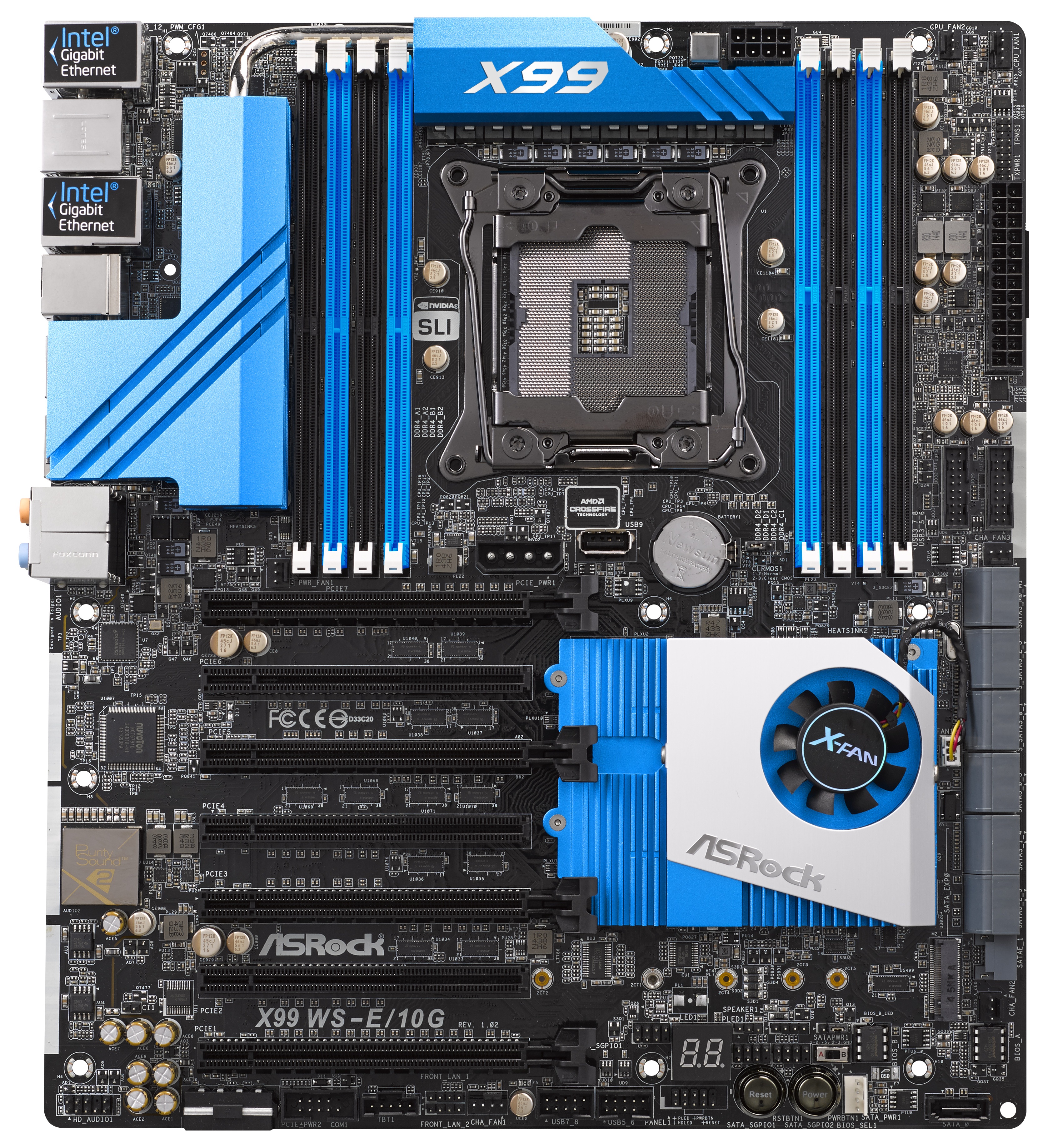
On the right hand side of the motherboard is our TPM header followed by the 24-pin ATX power connector and two USB 3.0 headers, where both of these come from the PCH. With the SATA ports there are twelve in total in this segment with the first two being powered by a Marvell controller. The next ten are from the PCH with the first six RAID capable, then the next four are not. As part of this final four there is also a SATA Express port coming from the chipset. For more connectivity we have a black SATA DOM port at the bottom of the board and a PCIe 2.0 x4 M.2 slot from the chipset supporting 2230 to 22110 sized devices. If a device is plugged into the final four SATA ports, the M.2 bandwidth drops to M.2 x2. This suggests that ASRock can partition some of the bandwidth from the second non-RAID AHCI controller in the chipset for M.2 usage, and that the second AHCI controller is in-part based on PCIe. This further implicates my prediction that the chipset is just turning into a mass of PCIe lanes / FPGA as required by the motherboard manufacturer.
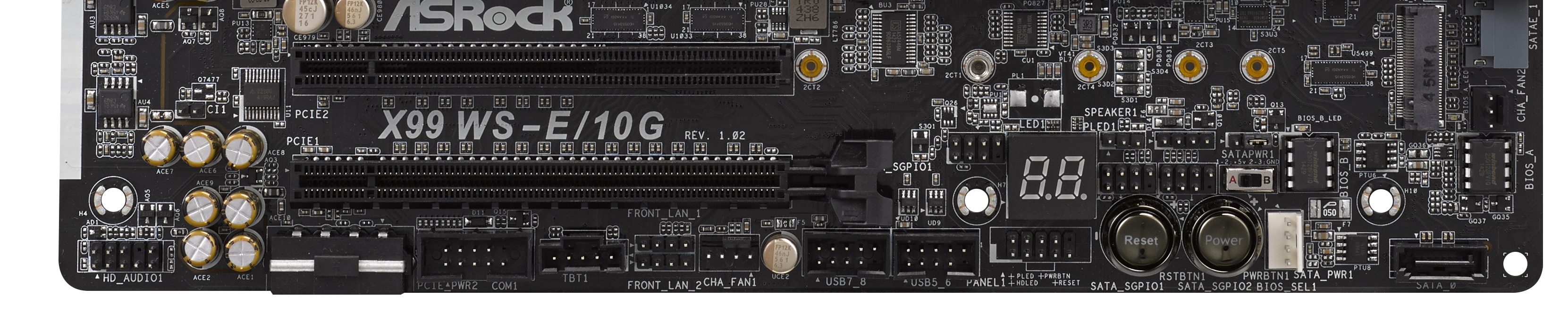
At the bottom of the motherboard are our power/reset buttons alongside the two-digit debug. The two BIOS chips are also here with a BIOS select switch, two SATA-SGPIO headers, two USB 2.0 headers, a COM header, a Thunderbolt header, two of the fan headers and that ugly molex power connector. As usual the front panel audio and control headers are here too, as well as two other headers designated FRONT_LAN, presumably to allow server builders to route the signals from the network ports to LEDs on the front of the case.
The audio subsystem uses an upgraded Realtek ALC1150 package, meaning an EMI shield, PCB separation and enhanced filter caps. The PCIe layout is relatively easy to follow:
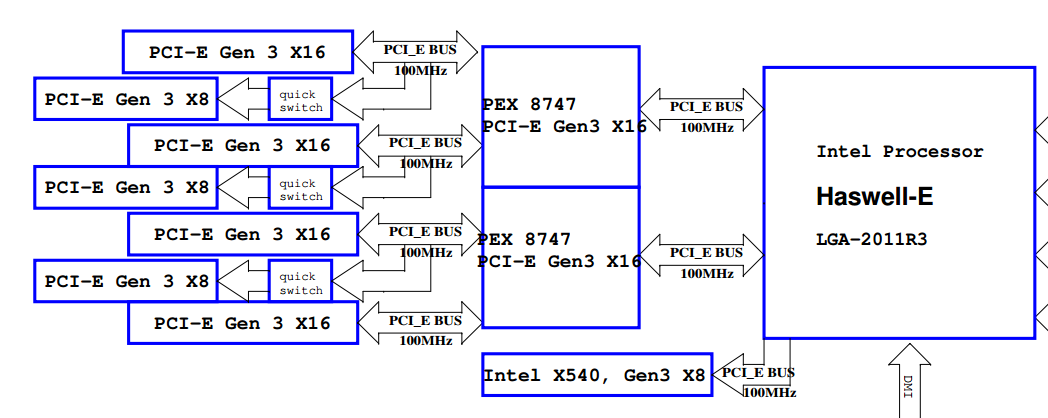
From the 40 PCIe lanes from the CPU, these are split into x16/x16/x8. The final x8 goes to the 10GBase-T controller, whereas the other lanes get filtered into one PLX controller each. This gives the effect of muxing 16 lanes into 32 (with an extra buffer), allowing each PLX controller to feed two x16 slots for a total of four PCIe 3.0 x16 (hence x16/x16/x16/x16 support). Three of these x16 slots are quick switched to x8 slots, creating x8/x8 from three of the x16 ports.
This means:
Four PCIe devices or less: x16/-/x16/-/x16/-/x16
Four to Seven PCIe devices: x8/x8/x8/x8/x8/x8/x16
So for anyone that wants to strap on some serious PCIe storage, RAID cards or single slot PCIe co-processors, everyone gets at least PCIe 3.0 x8 bandwidth.
For users on the i7-5820K, things are a little different but not so much. Due to only having 28 PCIe lanes, the outputs are split x16/x8/x4, with x4 going to the X540. This leaves x16 and x8 going to the PLX controllers, but in both cases each PLX chip will configure to 32 PCIe lanes, still giving an x16/x16/x16/x16 or x8/x8/x8/x8/x8/x8/x16 arrangement. With only four lanes, the two 10GBase-T ports are still designated to work with PCIe 3.0 x4 (given the original requirement of PCIe 2.0 x8 for the controller), but full bandwidth might not be possible according to Intel’s FAQ on the X540 range – check point 2.27 here.
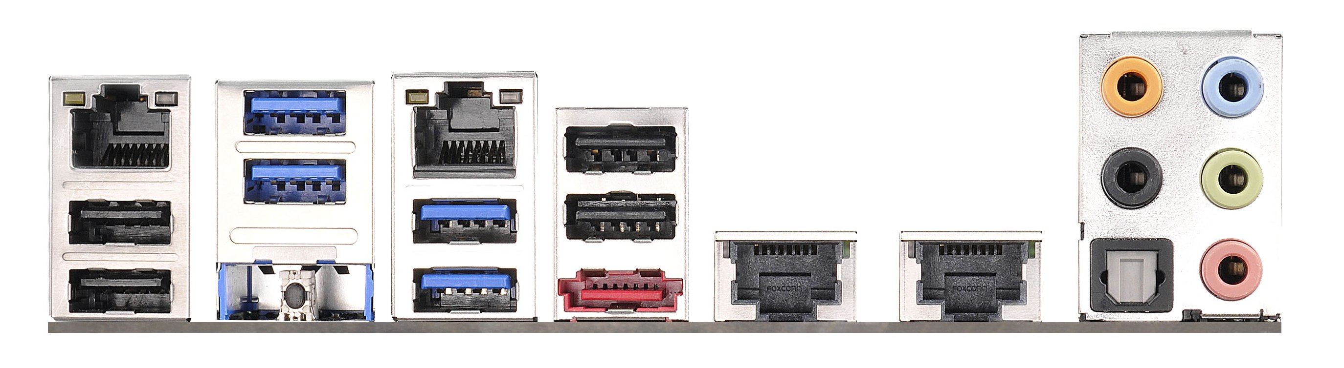
The rear panel removes any PS/2 ports and gives four USB 2.0 alongside four USB 3.0, with the latter coming from an ASMedia hub. The two network ports on the left are from Intel I210 controllers, whereas the two on the right are the 10GBase-T ports from the Intel X540-BT2 controller. There is a Clear_CMOS button, an eSATA port and the audio jacks to round off the set.
Board Features
| ASRock X99 WS-E/10G | |
| Price | US (Newegg) |
| Size | E-ATX |
| CPU Interface | LGA2011-3 |
| Chipset | Intel X99 |
| Memory Slots | Eight DDR4 DIMM slots Supporting up to 64 GB UDIMM, 128 GB RDIMM Up to Quad Channel, 1066-3200 MHz |
| Video Outputs | None |
| Network Connectivity | 2 x Intel I210 (1Gbit) 2 x Intel X540-BT2 (10GBase-T) |
| Onboard Audio | Realtek ALC1150 |
| Expansion Slots | 4 x PCIe 3.0 x16 3 x PCIe 3.0 x8 |
| Onboard Storage | 6 x SATA 6 Gbps, RAID 0/1/5/10 4 x S_SATA 6 Gbps, no RAID 2 x SATA 6 Gbps, Marvell 9172 1 x SATA Express 1 x M.2 PCIe 2.0 x4 / x2 |
| USB 3.0 | 4 x USB 3.0 on Rear Panel (ASMedia ASM1042 Hub) 2 x USB 3.0 Headers onboard (PCH) |
| Onboard | 12 x SATA 6 Gbps 1 x SATA DOM 1 x M.2 x4 2 x USB 2.0 Headers 2 x USB 3.0 Headers 5 x Fan Headers 1 x USB 2.0 Type-A TPM Header COM Header Thunderbolt Header 2 x FRONT_LAN Headers 2 x SATA_SPGIO Headers Power/Reset Switches Two Digit Debug BIOS Switch SATA DOM Power Front Panel Header Front Audio Header |
| Power Connectors | 1 x 24-pin ATX 1 x 8-pin CPU 2 x VGA Molex |
| Fan Headers | 2 x CPU (4-pin, 3-pin) 3 x CHA (4-pin, 2 x 3-pin) |
| IO Panel | 2 x USB 2.0 2 x USB 3.0 (ASMedia Hub) 2 x Intel I210 Gbit Network 2 x Intel X540-BT2 10GBase-T Network eSATA Clear_CMOS Button Audio Jacks |
| Warranty Period | 3 Years |
| Product Page | Link |


45 Comments
View All Comments
Jammrock - Monday, December 15, 2014 - link
You can achieve 10Gb speeds (~950MB/s-1.08Gb/s real world speeds) on a single point-to-point transfer if you have the right hardware and you know how to configure it. Out-of-the-box...not likely. The following assumes your network hardware is all 10Gb and jumbo frame capable and enabled.1. You need a source that can sustain ~1GB/s reads and a destination that can sustain ~1GB/s writes. A couple of high end PCIe SSD cards, RAID'ed SSDs or a RAMdisk can pull it off, and that's about it.
2. You need a protocol that supports TCP multi-channel. SMB3, when both source and destination are SMB3 capable (Win8+/2012+), does this by default. Multi-threaded FTP can. I think NFS can, but I'm not 100% certain...
3. You need RSS (Receive Side Scaling), LSO (Large Send/Segment Offloading), TCP window scaling (auto tuning) and TCP Chimney (for Windows), optionally RSC (Receive Side Coalescing), are setup and configured properly.
Even modern processors cannot handle 10Gb worth of reads on a single processor core, thus RSS needs setup with a minimum of 4 physical processor cores (RSS doesn't work on Hyperthreaded logical cores), possibly 8, depending on processor, to distribute receive load across multiple processors. You can do this via PowerShell (Windows) with the Set-NetAdapterRss cmdlet.
# example command for a 4 physical core proc w/ Hyerpthreading (0,2,4,6 are physical, 1,3,5,7 are logical....pretty much a rule of thumb)
Set-NetAdapterRss -Name "<adapter name>" -NumberOfReceiveQueues 4 -BaseProcessorNumber 0 -MaxProcessorNumber 6 -MaxProcessors 4 -Enabled
LSO is set in the NIC drivers and/or PowerShell. This allows Windows/Linux/whatever to create a large packet (say 64KB-1MB) and let the NIC hardware handle segmenting the data to the MSS value. This lowers processor usage on the host and makes the transfer faster since segmenting is faster in hardware and the OS has to do less work.
RSC is set in Windows or Linux and on the NIC. This does the opposite of LSO. Small chunks are received by the NIC and made into one large packet that is sent to the OS. Lowers processor overhead on the receive side.
While TCP Chimney gets a bad rap in the 1Gb world, it shines in the 10Gb world. Set it to Automatic in Windows 8+/2012+ and it will only enable on 10Gb networks under certain circumstances.
TCP window scaling (auto-tuning in the Windows world) is an absolute must. Without it the TCP windows will never grow large enough to sustain high throughput on a 10Gb connection.
4. Enable 9K jumbo frames (some people say no, some say yes...really depends on hardware, so test both ways).
5. Use a 50GB file or larger. You need time for the connection to ramp up before you reach max speeds. A 1GB file is way too small to test a 10Gb connection. To create a dummy file in Windows use fsutil: fsutil file createnew E:\Temp\50GBFile.txt 53687091200
This will normally get you in the 900 MB/s range on modern hardware and fast storage. LSO and TCP Chimney makes tx faster. RSS/RSC make rx faster. TCP multi-channel and auto-tuning give you 4-8 fast data streams (one for each RSS queue) on a single line. The end result is real world 10Gb data transfers.
While 1.25GB/s is the theoretical maximum, that is not the real world max. 1.08GB/s is the fastest I've gone on a single data transfer on 10Gb Ethernet. That was between two servers in the same blade chassis (essentially point-to-point with no switching) using RAM disks. You can't really go much faster than that due to protocol overhead and something called bandwidth delay product.
Ian Cutress - Monday, December 15, 2014 - link
Hi Jammrock, I've added a link in the main article to this comment - it is a helpful list of information for sure.For some clarification, our VMs were set for RAMDisk-to-RAMDisk operation, but due only having UDIMMs on hand the size of our RAMDisks was limited. Due to our internal use without a switch, not a lot else was changed in the operation, making it more of an out-of-the-box type of test. There might be scope for ASRock to apply some form of integrated software to help optimise the connection. If possible I might farm out this motherboard to Ganesh for use in future NAS reviews, depending on his requirements.
staiaoman - Monday, December 15, 2014 - link
wow. Such a concise summary of what to do in order to achieve high speed network transfers...something so excellent shouldnt just be buried in the comments on Anandtech (although if it has to be in the comments of a site, Anand or STH.com are clearly the right places ;-P). Thanks Jammrock!!Hairs_ - Monday, December 15, 2014 - link
Excellent comment, but it just underlines what a ridiculously niche product this is.Anyone running workloads like this surely isn't doing it using build it yourself equipment over a home office network?
While this sort of arrive no doubt is full of interesting concepts to research for the reviewer, it doesn't help 99% of builders or upgraders out there.
Where are the budget/midrange haswell options? Given the fairly stagnant nature of the amd market, what about an article on long term reliability? Both things which actually might be of interest to the majority of buyers.
Nope, another set of ultra-niche motherboard reviews for those spending several hundred dollars.
The reviews section on newegg is more use as a resource at this stage.
Harald.1080 - Monday, December 15, 2014 - link
It's not that complicated.We set up 2 xeon E5 single socket machines with esxi 5.1, some guests on both machines, a 800€ 10g switch, and as the NAS backup machine a xeon E3 with 2 samsung 840pro in raid0 as fastcache in front of a fast raid5 disk system. NFS. All 3 machines with intel single port 10g. Jumbo frames.
Linux vm guest A to other hosts vm guest B with ramdiskt 1GB/s from the start.
Vmware hosts to NAS (the xeon E3 NFS System) with ssd cache: 900 MB/s write. w/o cache: 20 MB/s
Finally used Vmdk disk tools to copy snapshotted disks for backup. Faster than file copy.
I think, doing the test on the SAME MACHINE is a bad idea. Interrupt handlers will have a big effect on the results. What about Queues?
shodanshok - Tuesday, December 16, 2014 - link
I had similar experience on two Red Hat 6 boxes using Broadcomm's NetXtreme II BCM57810 10 Gb/s chipset. The two boxes are directly connected by a Cat 6e cable, and the 10GBASE-T adapters are used to synchronize two 12x 15K disks arrays (sequential read > 1.2 GB/s)RSS is enabled by default, and so are TCO and the likes. I manually enabled jumbo frames on both interface (9K MTU). Using both netperf and iperf, I recorded ~9.5 Gb/s (1.19 GB/s) on UDP traffic and slightly lower (~9.3 Gb/s) using TCP traffic.
Jumbo frames really made a big difference. A properly working TCP windows scaling alg is also a must have (I had two 1 Gb/s NICs with very low DRBD throughput - this was due to bad window scaling decision from the linux kernel when using a specific ethernet chip driver).
Regards.
jbm - Saturday, December 20, 2014 - link
Yes, the configuration is not easy, and you have to be careful (e.g. if you want to use SMB multichannel over several NICs, you need to have them in separate subnets, and you should make sure that the receive queues for the NICs are not on the same CPU cores). Coincidentally, I configured a couple servers for hyper-v at work recently which use Intel 10Gb NICs. With two 10Gb NICs, we get live migration speeds of 2x 9.8Gb/s, so yes - it does work in real life.Daniel Egger - Monday, December 15, 2014 - link
> The benefits of 10GBase-T outside the data center sound somewhat limited.Inside the data center the benefits are even more limited as there's usually no problem running fibre which is easier to handle, takes less volume, uses less power and allows for more flexibility -- heck, it even costs less! No sane person would ever use 10GBase-T in a datacenter.
The only place where 10GBase-T /might/ make sense is in a building where one has to have cross room connectivity but cannot run fibre; but better hope for a good Cat.7 wiring and have the calibration protocol ready in case you feel the urge to sue someone because it doesn't work reliably...
gsvelto - Monday, December 15, 2014 - link
There's also another aspect that hasn't been covered by the review: the reason why 10GBase-T is so slow when used by a single user (or when dealing with small transfers, e.g. NFS with small files) is that it's latency is *horrible* compared to Direct Attach SFP+. A single hop over an SFP+ link can take as little as 0.3µs while one should expect at least 2µs per 10GBase-T link and it can be higher.This is mostly due to the physical encoding (which requires the smallest physical frame transferable to be 400 bytes IIRC) and the heavy DSP processing needed to extract the data bits from the signal. Both per-port price and power are also significantly.
In short, if you care about latency or small-packet transfers 10GBase-T is not for you. If you can't afford SFP+ then go for aggregated 1GBase-T links, they'll serve you well, give you lower latency and redundancy as the cherry on top.
shodanshok - Tuesday, December 16, 2014 - link
This is very true, but it really depend on the higher-level protocol you want to use over it.IP over Ethernet is *not* engineered for latency. Try to ping your localhost (127.0.0.1) address: on RHEL 6.5 x86-64 running on top of a Xeon E5-2650 v2 (8 cores at 2.6 GHz, with performance governor selected, no heavy processes running) RTT times are about 0.010 ms, or about 10 usec. On-way sending is about half, at 5us. Adding 2us is surely significant, but hardly world-changer.
This is for a localhost connection with a powerful processor and no other load. On a moderately-loaded, identical machine, the localhost RTT latency increase to ~0.03ms, or 15us for one-way connection. RTT for one machine to another is ranging from 0.06ms to 0.1ms, or 30-50us for one way traffic. As you can see, the 2-4us imposed by the 10Base-T encoding/decoding is rapidly fading away.
IP creators and stack writers know that. They integrated TCP window scaling, Jumbo frames et similar to overcome that very problem. Typically, when very low-latency is needed, some lightweight protocol is used *on top* of these low-latency optical links. Heck, even PCI-E, with its sub-us latency is often too slow for some kind of workload. For example, some T-series SPARC CPU include 10GB Ethernet links rightly into the CPU packages, using dedicated low-latency internal bus, but using classical IP schemes on top of these very fast connection will not give you very high gain over more pedestrian 10Base-T ethernet cards...
Regards.